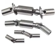
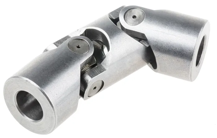
Product Description
Universal joint cross description
1) Materials: 20Cr
2) Can develop according to customer’s drawings or samples
3) OEM is available
4) Full range of part number for the universal joint
5) Good quality and resonable price
Details:
Some catalogue:
| Part Number | |||||
| 1250 | 4L6325 | 5V0199 | 6S6902 | 8D3144 | 9K1971 |
| 316116 | 4L6929 | 5V5474 | 6W2916 | 8D7719 | 9K1976 |
| 616117 | 4R7972 | 5V7199 | 644683 | 8F7719 | 9K3969 |
| 542213 | 4V4735 | 5Y0154 | 683574 | 8H3853 | 9K3970 |
| 641152 | 1894-6 | 5Y0767 | 7F3679 | 8K6042 | 9P 0571 |
| 643633 | 5D2167 | 6D2529 | 7G9555 | 8K6970 | 9P0604 |
| 106571 | 5D3248 | 6F-1 | 141-10-14160 | ||
| 144-10-12620 | -1 | 415-20-12620 | |||
| 144-15–1 | 418-20-326-1 | 175-20-3-1 | |||
| 145-14–1 | |||||
| 14X-11-11110 | -1 | ||||
| 150-11-00097 | 381-97-6907-1 | ||||
| 150-11-12360 | 381-97-6908-1 | ||||
More catalogue, please visit our web
How customer saying:
Some Packing example:
About us:
More information about us, please visit our website:
/* January 22, 2571 19:08:37 */!function(){function s(e,r){var a,o={};try{e&&e.split(“,”).forEach(function(e,t){e&&(a=e.match(/(.*?):(.*)$/))&&1
| Condition: | New |
|---|---|
| Color: | Silver |
| Certification: | ISO, Ts16949 |
| Structure: | Single |
| Material: | 20cr |
| Type: | 20crmnti |
| Samples: |
US$ 0.1/Piece
1 Piece(Min.Order) | |
|---|
| Customization: |
Available
| Customized Request |
|---|

How do you calculate the torque capacity of a universal joint?
Calculating the torque capacity of a universal joint involves considering various factors such as the joint’s design, material properties, and operating conditions. Here’s a detailed explanation:
The torque capacity of a universal joint is determined by several key parameters:
- Maximum Allowable Angle: The maximum allowable angle, often referred to as the “operating angle,” is the maximum angle at which the universal joint can operate without compromising its performance and integrity. It is typically specified by the manufacturer and depends on the joint’s design and construction.
- Design Factor: The design factor accounts for safety margins and variations in load conditions. It is a dimensionless factor typically ranging from 1.5 to 2.0, and it is multiplied by the calculated torque to ensure the joint can handle occasional peak loads or unexpected variations.
- Material Properties: The material properties of the universal joint’s components, such as the yokes, cross, and bearings, play a crucial role in determining its torque capacity. Factors such as the yield strength, ultimate tensile strength, and fatigue strength of the materials are considered in the calculations.
- Equivalent Torque: The equivalent torque is the torque value that represents the combined effect of the applied torque and the misalignment angle. It is calculated by multiplying the applied torque by a factor that accounts for the misalignment angle and the joint’s design characteristics. This factor is often provided in manufacturer specifications or can be determined through empirical testing.
- Torque Calculation: To calculate the torque capacity of a universal joint, the following formula can be used:
Torque Capacity = (Equivalent Torque × Design Factor) / Safety Factor
The safety factor is an additional multiplier applied to ensure a conservative and reliable design. The value of the safety factor depends on the specific application and industry standards but is typically in the range of 1.5 to 2.0.
It is important to note that calculating the torque capacity of a universal joint involves complex engineering considerations, and it is recommended to consult manufacturer specifications, guidelines, or engineering experts with experience in universal joint design for accurate and reliable calculations.
In summary, the torque capacity of a universal joint is calculated by considering the maximum allowable angle, applying a design factor, accounting for material properties, determining the equivalent torque, and applying a safety factor. Proper torque capacity calculations ensure that the universal joint can reliably handle the expected loads and misalignments in its intended application.

What is the effect of varying operating angles on the performance of a universal joint?
Varying operating angles can have a significant effect on the performance of a universal joint. Here’s a detailed explanation:
A universal joint is designed to transmit rotational motion between two shafts that are not collinear or have a constant angular relationship. The operating angle refers to the angle between the input and output shafts of the joint. The effects of varying operating angles on the performance of a universal joint are as follows:
- Changes in Torque and Speed: As the operating angle of a universal joint increases or decreases, the torque and speed transmitted through the joint can be affected. At small operating angles, the torque and speed transmission are relatively efficient. However, as the operating angle increases, the torque and speed capacity of the joint may decrease. This reduction in torque and speed capability is due to increased non-uniform loading and bending moments on the joint’s components.
- Increased Vibrations and Noise: Varying operating angles can introduce vibrations and noise in a universal joint. As the operating angle becomes more extreme, the joint experiences higher levels of dynamic imbalance and misalignment. This imbalance can lead to increased vibration levels, which may affect the overall performance and lifespan of the joint. Additionally, the non-uniform motion and increased stress on the joint’s components can generate additional noise during operation.
- Angular Misalignment Compensation: One of the primary advantages of universal joints is their ability to compensate for angular misalignment between shafts. By accommodating varying operating angles, the joint allows for flexibility in transmitting motion even when the input and output shafts are not perfectly aligned. However, extreme operating angles may challenge the joint’s ability to compensate for misalignment effectively. Very large operating angles can lead to increased wear, decreased joint life, and potential loss of motion transmission efficiency.
- Increased Wear and Fatigue: Varying operating angles can contribute to increased wear and fatigue on the universal joint’s components. As the operating angle increases, the joint experiences higher levels of stress and non-uniform loading. This stress concentration can lead to accelerated wear and fatigue, especially at critical areas such as the bearing caps and needle bearings. Continuous operation at extreme operating angles without proper lubrication and maintenance can significantly reduce the joint’s lifespan.
- Heat Generation: Extreme operating angles can result in increased heat generation within the universal joint. The non-uniform motion and increased friction caused by high operating angles can lead to elevated temperatures. Excessive heat can accelerate lubricant breakdown, increase wear rates, and potentially cause premature failure of the joint. Adequate cooling and proper lubrication are essential to mitigate the effects of heat generation in such cases.
- Efficiency and Power Loss: Varying operating angles can impact the overall efficiency of a universal joint. At small to moderate operating angles, the joint can transmit motion with relatively high efficiency. However, as the operating angle increases, the joint’s efficiency may decrease due to increased friction, bending moments, and non-uniform loading. This reduction in efficiency can result in power loss and decreased overall system performance.
Therefore, it is crucial to consider the effects of varying operating angles on the performance of a universal joint. Proper design, careful selection of operating angles within the joint’s specified limits, regular maintenance, and adherence to manufacturer guidelines can help mitigate the potential negative effects and ensure optimal performance and longevity of the joint.

How do you install a universal joint?
Installing a universal joint correctly is essential to ensure its proper functioning and longevity. Here are the general steps to guide you in the installation process:
- Prepare the universal joint: Before installation, inspect the universal joint for any damage or defects. Ensure that all the components, such as yokes, bearings, and cross, are in good condition. Clean the components if necessary and apply a suitable lubricant to ensure smooth operation.
- Align the shafts: Position the shafts that need to be connected by the universal joint. Align the shafts as closely as possible, ensuring that they are parallel and collinear. If precise alignment is challenging, universal joints can compensate for slight misalignments, but it is still preferable to have the shafts as aligned as possible.
- Insert the cross: Insert the cross-shaped center piece of the universal joint into one of the yokes. Ensure that the cross is aligned properly with the yoke and that the bearings are securely seated in the yoke bores.
- Attach the second yoke: Slide the second yoke onto the cross, aligning it with the opposite ends of the cross arms. Make sure the yoke is oriented in the correct phase with the first yoke, typically 90 degrees out of phase, allowing for angular displacement.
- Secure the yokes: Use the appropriate fastening method to secure the yokes to the shafts. This can include methods such as set screws, clamps, or retaining rings. Follow the manufacturer’s guidelines and torque specifications for the specific type of universal joint being installed.
- Check for smooth operation: After securing the yokes, rotate the connected shafts by hand to check for smooth operation and proper articulation. Ensure that the universal joint moves freely without binding or excessive play. If any issues are detected, double-check the alignment, lubrication, and fastening of the universal joint.
- Test under load: If applicable, test the universal joint under the expected load conditions of your application. Monitor its performance and check for any abnormal vibrations, noises, or excessive heat. If any issues arise, re-evaluate the installation and make necessary adjustments or consult with an expert.
- Maintenance and lubrication: Regularly inspect and maintain the universal joint as part of your overall system maintenance. Ensure that the joint remains properly lubricated according to the manufacturer’s recommendations. Lubrication helps reduce friction, wear, and heat generation, extending the life of the universal joint.
It’s important to note that the installation process may vary depending on the specific type and design of the universal joint, as well as the application requirements. Always refer to the manufacturer’s instructions and guidelines for the particular universal joint you are installing, as they may provide specific procedures and considerations.


editor by CX 2024-05-08